Bench Notes › Articles › Cables
Article · 3 min readThe #1 XLR mistake isn’t your soldering.
By [AUTHOR] · Sep 30, 2026 · Updated Oct 2
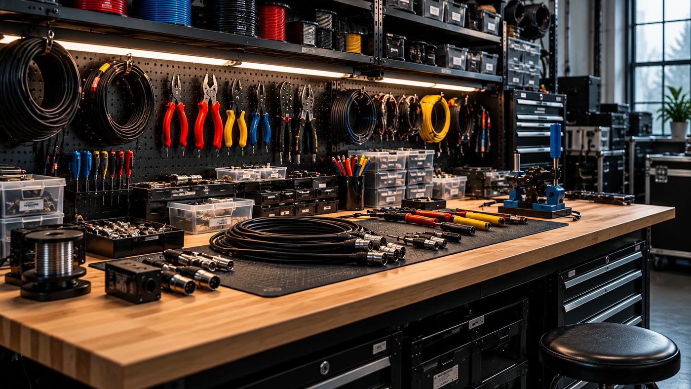
It’s guessing which pin is which. Flip the connector over and the solder side looks mirrored. Most bad XLR cables we see were built by someone who soldered beautifully onto the wrong pin.
Read the numbers
Every XLR insert has tiny molded numbers next to the cups (see the XLR 3-pin entry for the pin explorer and bench card). Pin 1 is shield, pin 2 is hot, pin 3 is cold. Read them on every connector, every time, both ends. Never go by position.
Then pick your colors
Wire colors aren’t standardized. Choose a scheme, write it on the bench, and verify both ends with a meter before the cable touches anything.

The free 5-page Cable Bench Guide. Same offer as our social posts: comment SOLDER there, or take it here.
Get the guidePinout reference
| Pin | Carries |
|---|---|
| 1 | Shield / chassis reference |
| 2 | Hot (+), non-inverting |
| 3 | Cold (−), inverting |
Related
The XLR Wiring Mistake That Keeps Coming Back · Bad Solder Joints: What to Look For Before They Fail · Course: Build a basic XLR cable