Bench Notes › Articles › Build
Article · 1 min readBad Solder Joints: What to Look For Before They Fail.
By Thomas Popp · Oct 7, 2026
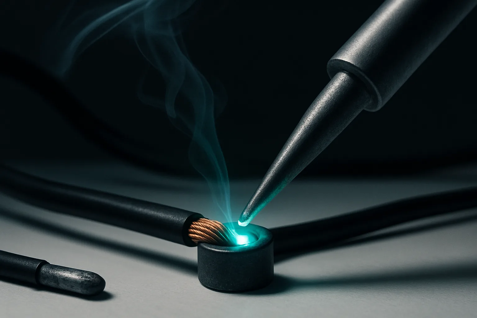
Most cable failures on set are not wire failures. They are solder-joint failures that looked fine when the cable left the bench. A joint can pass a continuity test today and crack under the first tug tomorrow, and the difference between a joint that survives and one that quits is visible - if you know what to look at. Learn the look of a joint that is about to fail, and you stop shipping time bombs.
The four ways a joint goes wrong
Every bad joint falls into one of four failure modes, and each has a distinct visual signature.
Insufficient heat is the classic. The solder never fully flows, so it balls up on the surface instead of wetting both the wire and the pin. The joint sits proud and rounded with visible gaps at the edges - the solder is sitting on the metal, not joined to it. It will fail the first time the cable flexes.
Excess solder is the opposite sin. A big blob covers a joint where the solder never actually bonded to the pin underneath - more solder, more hiding. If the joint only looks right because there is a lot of solder on it, the solder is concealing the problem, not fixing it.
Contamination - flux residue, oxidation, finger oils - leaves solder that beads instead of spreading, with a rough, raised edge where it refused to wet the metal. This is why handling the stripped conductor with bare fingers costs you: the oil on your skin is enough to break the wetting.
And then there is movement while cooling, the disturbed joint. The solder freezes mid-crystal and the surface turns dull, grainy, crystalline instead of smooth. It may conduct today, but it is cracked inside, and vibration will finish the job.
What a good joint actually looks like
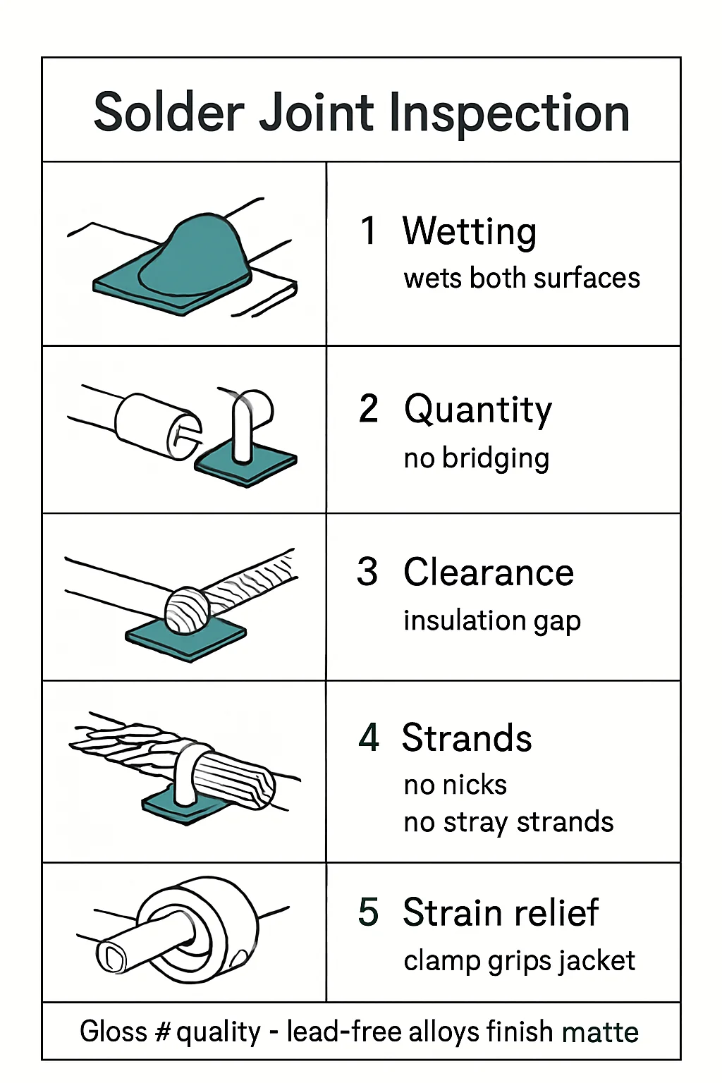
A good joint wets both surfaces with a smooth, concave fillet and feathered edges - the solder flows out thin where it meets the metal instead of stopping in a hard line. One caution on judging by appearance alone: shiny versus dull is not pass/fail. Lead-free solder is naturally duller than leaded solder, so judge wetting and shape, not gloss. A dull lead-free joint with a perfect concave fillet is fine; a shiny blob with gaps at the edges is not.
The test that finds the quitters
Inspection catches most failures, but the final proof is mechanical. After soldering an XLR or TRS connector, give the wire a firm tug - harder than a camera assistant ever would. A joint that is going to fail would rather fail on your bench than on set. Then re-test continuity on every pin while flexing the cable at the connector:
intermittents show up under movement, never while the cable lies still. The same logic applies everywhere on the bench - test the thing the way it will actually be used, with the forces it will actually see.
Bench takeaway: a joint that passes a static continuity test but can't survive a firm tug is a failure waiting for an audience.
Pinout reference
| Pin | Carries |
|---|---|
| T | Hot (+) |
| R | Cold (−) |
| S | Shield |
| Pin | Carries |
|---|---|
| 1 | Shield / chassis reference |
| 2 | Hot (+), non-inverting |
| 3 | Cold (−), inverting |
Related
The XLR Wiring Mistake That Keeps Coming Back · The One Thing Everyone Forgets Before Soldering · Course: Build a basic XLR cable