Bench Notes › Articles › Build
Article · 1 min readThe XLR Wiring Mistake That Keeps Coming Back.
By Thomas Popp · Oct 7, 2026
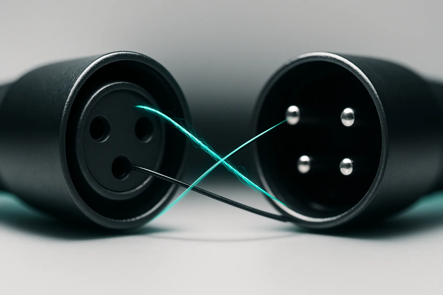
Every repair bench has one: a cable that "works" but phases cancel, levels are wrong, or a balanced line hums. The cause is almost always pins 2 and 3 swapped - the oldest wiring mistake in the book, and it keeps returning because people wire from memory instead of verifying.
Why it keeps happening
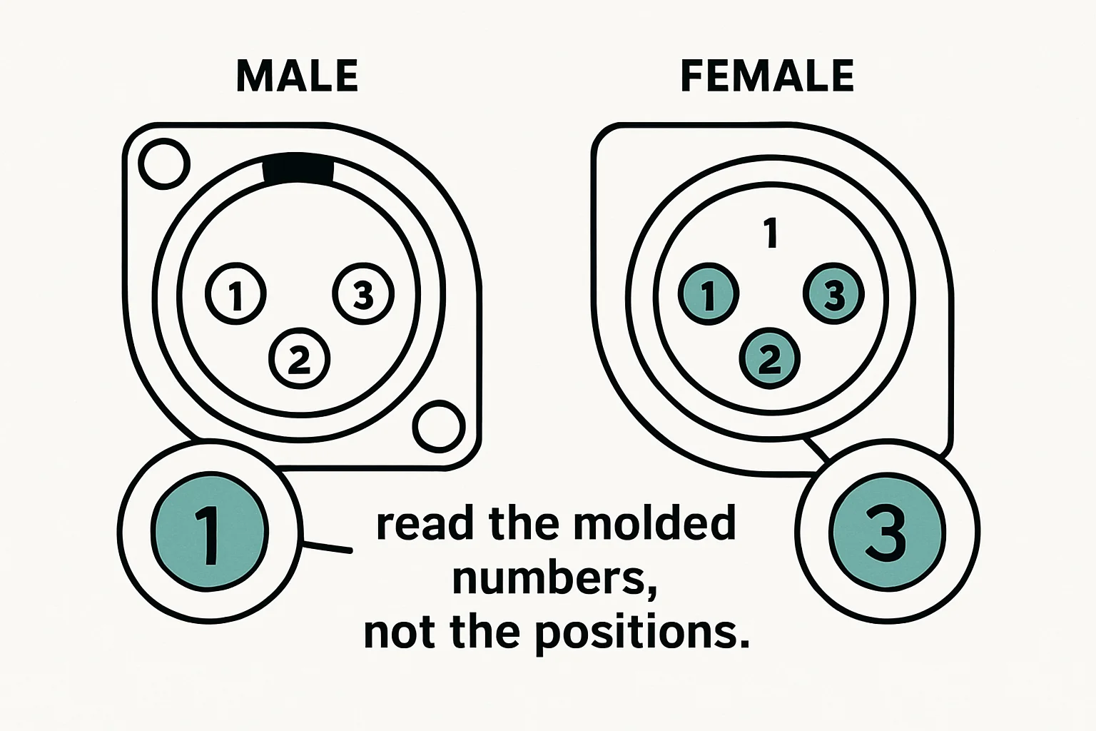
Nobody sits down intending to wire a cable wrong. They just don't check. The pin roles are simple enough to memorize, so people skip the one step that matters: looking at the actual connector in their hand. And here's the trap - male and female XLRs present their pins as mirror images, so a layout memorized for one gender reads backwards on the other. If you learned the positions on a male connector and you're soldering a female, your memory is lying to you. Read the pin numbers molded into the connector's dielectric. They're stamped right there in the plastic. Trust the plastic, not your memory.
What correct looks like
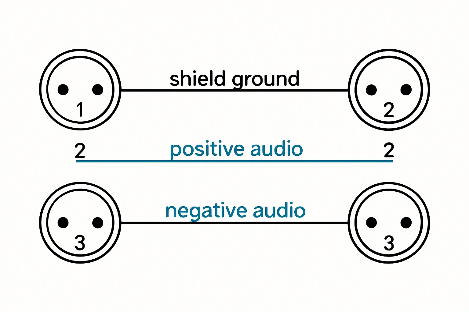
Pin roles on a balanced XLR are fixed: pin 1 is ground/shield, pin 2 is hot (+), pin 3 is cold (-). That's the AES/EBU standard wiring the vault catalog verifies for PB-XLRF3-XLRM3. A standard mic cable runs pin-to-pin: 1 to 1, 2 to 2, 3 to 3, female end to male end. No crossover, no cleverness.
Why swapped pins "work"
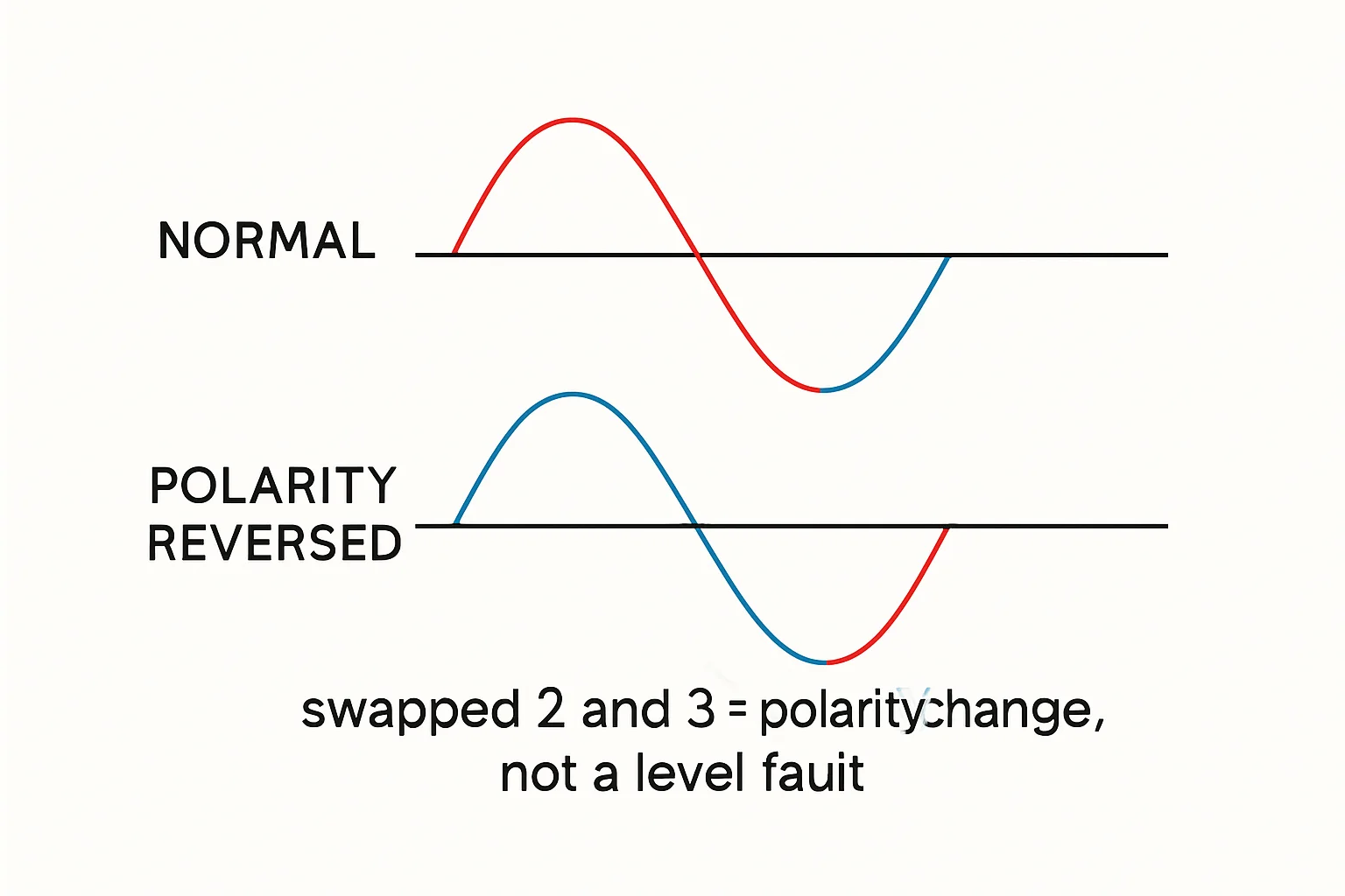
This is why the mistake survives: swapping 2 and 3 reverses polarity, and on one mic alone, in isolation, that's inaudible. The cable passes signal, the meter reads fine, and nobody notices - until it matters. Then it matters everywhere at once: two mics on the same source cancel each other out, levels don't match the rest of the rig, and a balanced line that should be quiet starts humming. The cable behaves perfectly in exactly the conditions where you'd check it, and fails in exactly the conditions where it counts.
The verification habit
Wire to the molded numbers - shield to pin 1, hot to pin 2, cold to pin 3 - then confirm pin-to-pin with a meter after soldering, before you screw the shell on. Checking while the joints are still accessible costs thirty seconds. Finding the mistake after the cable is sealed means opening it back up and doing it again. And keep a wired reference cable on the bench - one known-good mic cable. When a soldered cable behaves oddly, comparing it side by side with the reference beats re-reading any diagram.
Bench takeaway: Read the numbers stamped on the connector, wire 1-shield, 2-hot, 3-cold, and meter it before the shell goes on.
Pinout reference
| Pin | Carries |
|---|---|
| 1 | Shield / chassis reference |
| 2 | Hot (+), non-inverting |
| 3 | Cold (−), inverting |
Related
Bad Solder Joints: What to Look For Before They Fail · The One Thing Everyone Forgets Before Soldering · Course: Build a basic XLR cable