Bench Notes › Articles › Test
Article · 2 min readThree Tests Every New Audio Cable Should Pass.
By Thomas Popp · Oct 7, 2026
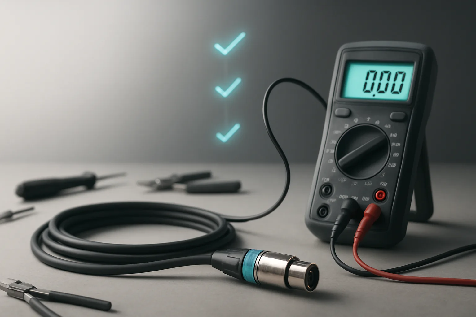
Fresh off the bench or fresh out of the bag, a new cable is unproven. "It worked last time" is not a test, and "it lit up the cable tester once" is barely better. Three checks - all done on a disconnected cable with no signal required - take about five minutes and catch the defects that embarrass you on set. Do them before the cable earns a spot on the wall, and do them again any time a cable comes back with a question mark over it.
Test one: correct pin mapping
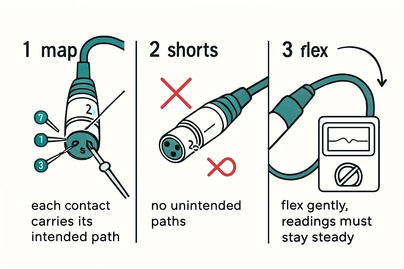
With the cable disconnected at both ends, meter continuity from pin to pin, end to end. On a standard mic cable (PB-XLRF3-XLRM3) that's pin 1 to 1 for ground/shield, pin 2 to 2 for hot, pin 3 to 3 for cold - straight through, no crossings. Whatever cable you're testing, compare against its documented pinout; any reading that disagrees with the sheet fails the cable. This is the step people skip because the cable "looks right," and it's the step that catches the factory miswire and the re-termination where someone read the pinout from the wrong end. The documented pinout is the authority, not the colors of the wires and not your memory.
Test two: no unintended shorts
With the far end unmated, check every pin against every other pin and the shell. You want infinite resistance everywhere except the mapped pairs from test one. A short between pin 1 and 2 on an XLR is a silent cable killer: it passes a quick "does it buzz" test, the cable looks fine in a fast field check, and then it fails the gig because phantom power or a ground fault behaves differently under load than under a continuity beep. This test is the one that separates a real QC pass from a cable-tester blink. Be methodical about the pairs: 1-to-2, 1-to-3, 2-to-3, and each pin to the shell. Skipping a pair is how a short hides.
Test three: stability under gentle movement
Hold one probe steady and flex the cable right where it enters each connector while watching the meter. You're simulating exactly what happens on set - the connector end is where cables bend, get stepped near, and get tugged. A continuity reading that flickers means a stressed solder joint or a conductor about to break inside the jacket. That's a tag for re-termination, not the wall. Note the qualifier: gentle movement. You're not trying to break the cable; you're looking for the joint that's already on its way out. A good cable's readings don't move when you flex it.
Log it or it didn't happen
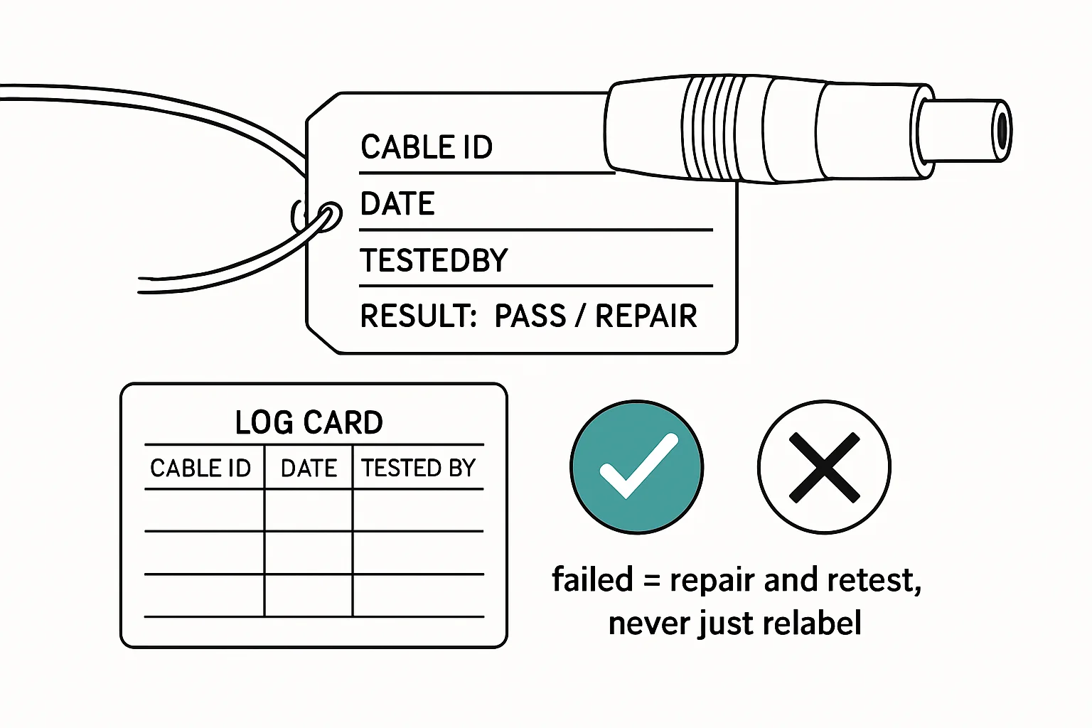
Write the results down - cable ID, date, pass or fail, and which test failed if one did. When that cable comes back from the field with a problem, you'll have a baseline instead of a memory. And when a pattern shows up say, the third cable from the same batch failing test three - the log is what turns a hunch into a decision to retire the batch.
Bench takeaway: pin mapping, shorts, and movement - five minutes on a disconnected cable, and no cable touches a gig without passing all three.
Pinout reference
| Pin | Carries |
|---|---|
| 1 | Shield / chassis reference |
| 2 | Hot (+), non-inverting |
| 3 | Cold (−), inverting |
Related
Your Cable Looks Fine. So Why Doesn't It Work? · The Wiggle Test: Catching a Cable That Only Fails Sometimes · Course: Build a basic XLR cable